Finite Element Analysis is a powerful tool that allows us to predict and optimize the behavior of a structure or system under different loading conditions. It has become an essential part of the engineering design process.

Contents
What is Finite element analysis, FEA?
Finite Element Analysis (FEA) is a powerful numerical method used to analyze and solve complex engineering problems. It is widely used in a variety of fields including aerospace, mechanical, civil, and biomedical engineering. The method involves dividing a complex structure or system into small, manageable elements and solving for unknown variables such as displacement, stress, and strain.
FEA has become an essential tool for engineers in the design process. It allows for the simulation and prediction of a product's behavior under different loading conditions. This enables engineers to identify potential failure points and optimize designs for strength, safety, and efficiency. In the past, engineers would rely on physical testing and trial-and-error methods to test a design. However, FEA allows for virtual testing, which is not only more efficient but also much less expensive.

Example of FEA in engineering component
A step-by-step guide on how to perform FEA.
Performing a Finite Element Analysis (FEA) can seem daunting, but with a step-by-step approach, it can be a straightforward process. FEA involves three main phases: pre-processing, solution, and post-processing.
Pre-processing Phase:
Define the problem and create a model of the system or structure to be analyzed. This can be done using computer-aided design (CAD) software or by creating a model manually.
Discretize the model into smaller, manageable elements. This is known as meshing and can be done automatically or manually.
Apply the appropriate boundary conditions and load conditions to the model. This step is crucial as it defines the conditions under which the analysis will be performed.
Solution Phase:
Solve for the unknown variables, such as displacement, stress, and strain. This is done using specialized software that can solve the equations generated in the previous steps.
The results will be saved in a format that can be used for post-processing.
Post-processing Phase:
Analyze and interpret the results to make design decisions or predictions about the behavior of the system. This can be done using visualization software that allows for the creation of contour plots, deformed shape plots, and other types of plots.
Verify the results with experimental or analytical methods. This step is important to ensure the accuracy and reliability of the analysis.
It's important to note that the above steps are a general guide and may vary depending on the specific software and type of analysis being performed. Additionally, pre-processing and post-processing phases may require iterative process to reach the desired results.
In conclusion, performing a Finite Element Analysis involves several steps, including pre-processing, solution, and post-processing. By following a step-by-step approach, engineers can efficiently and accurately analyze and predict the behavior of a structure or system under different loading conditions. This allows for the optimization of designs for strength, safety, and efficiency.

example of FEA process
Explanation of the different types of FEA (linear and non-linear, static and dynamic)
Finite Element Analysis (FEA) is a powerful numerical method that can be used to analyze a wide range of engineering problems. However, not all problems are the same, and different types of FEA are required to accurately analyze and solve different types of problems. The two main categories of FEA are linear and non-linear, and within each category, there are static and dynamic analyses.
Linear FEA: Linear FEA is used to analyze problems where the material behavior is linear and the loading conditions are small. This type of analysis is used to predict the behavior of structures or systems under small loads and small displacements. Linear FEA can be further divided into static and dynamic analyses.
Static Linear FEA: Static Linear FEA is used to analyze problems where the loading conditions are static, meaning that the loading does not change with time. This type of analysis is used to predict the behavior of structures or systems under constant loads and constant displacements.
Dynamic Linear FEA: Dynamic Linear FEA is used to analyze problems where the loading conditions are dynamic, meaning that the loading changes with time. This type of analysis is used to predict the behavior of structures or systems under time-dependent loads and time-dependent displacements.
Non-linear FEA: Non-linear FEA is used to analyze problems where the material behavior is non-linear, and the loading conditions are large. This type of analysis is used to predict the behavior of structures or systems under large loads and large displacements. Non-linear FEA can also be divided into static and dynamic analyses.
Static Non-Linear FEA: Static Non-Linear FEA is used to analyze problems where the loading conditions are static, and the material behavior is non-linear. This type of analysis is used to predict the behavior of structures or systems under constant loads and non-linear displacements.
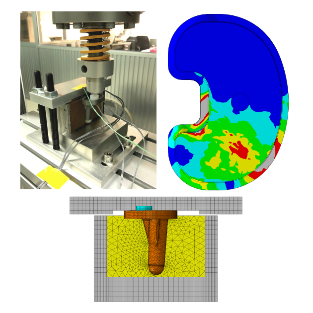
For example: At NRP, we understand the importance of understanding the localized mechanical properties of materials, such as fused silica, in order to optimize their performance and safety. Conventional tensile testing is not always able to provide this information, which is why our team of engineers uses an inverse numerical analysis approach. This involves using a load-displacement curve from nanoindentation testing and applying three-dimensional elastic-plastic finite element analysis (FEA) to deduce the mechanical properties.
Our engineers adjust the assumed mechanical properties until the numerical curve corresponds to the experimental curve. This allows us to estimate the localized mechanical properties in the vicinity of an indentation. The process of inverse numerical analysis is time-consuming and requires the expertise of experienced researchers. To address this, we propose a systematic adjustment of mechanical properties to obtain a satisfactory load-displacement curve.
This approach can be used to evaluate the localized stress-strain behavior of fused silica and other materials. By using this approach, NRP is able to provide our customers with more accurate and detailed information about the mechanical properties of the materials we process and use.
For more detail click here

Nanoindentation testing using FEA
Dynamic Non-Linear FEA: Dynamic Non-Linear FEA is used to analyze problems where the loading conditions are dynamic, and the material behavior is non-linear. This type of analysis is used to predict the behavior of structures or systems under time-dependent loads and non-linear displacements.
For example: At NRP, we specialize in providing advanced solutions for material processing using techniques such as equal-channel angular pressing (ECAP). To understand the effects of multi-pass ECAP processing on a circular cross-sectional workpiece made of a Cu-Zr alloy, our team of engineers performed a 3D Finite Element Method (FEM) simulation using ABAQUS/Explicit software.
The simulation aimed to investigate the distribution of plastic strain, homogeneity of strain, and the occurrence of a steady-state zone in the workpiece. The results revealed that after one pass, a strain inhomogeneity developed due to the formation of a corner gap in the outer corner of the die. The study also found that the average plastic strain and the degree of homogeneity both increase as the number of ECAP passes increases. Furthermore, the steady-state zone was identified in the middle section of the ECAP workpiece, and it was calculated to extend over a length of approximately 40 mm along the longitudinal axis for the Cu-Zr alloy.
This study provides valuable insights for NRP's engineers and researchers in the field of material processing to understand the behavior of the material under multi-pass ECAP processing and ensure the longevity and safety of our processed materials.
For more detail click here

ECAP process using FEA
In conclusion, Finite Element Analysis can be divided into two main categories, linear and non-linear, and within each category, there are static and dynamic analyses. Linear FEA is used to analyze problems where the material behavior is linear and the loading conditions are small, while non-linear FEA is used to analyze problems where the material behavior is non-linear and the loading conditions are large. Understanding the different types of FEA and when to use them is essential for accurate and efficient analysis and prediction of the behavior of structures or systems under different loading conditions.
Real-world examples of how FEA is used in various engineering fields such as aerospace, mechanical, and civil engineering.
Finite Element Analysis (FEA) is a widely used numerical method in various engineering fields, including aerospace, mechanical, and civil engineering. In this section, we will take a look at some real-world examples of how FEA is used in these fields to improve the design and performance of structures and systems.
Aerospace Engineering: In the aerospace industry, FEA is a crucial tool for analyzing the behavior of aircraft structures under various loading conditions such as flight loads, landing loads, and bird strikes. It is also used to analyze the behavior of rocket and missile structures under high-temperature and high-pressure conditions. Additionally, FEA is used to analyze the behavior of composite materials, which are commonly used in the aerospace industry. Furthermore, FEA is extensively used in the analysis of jet engines and turbine components, which are critical for ensuring safety and performance during operation. The application of FEA in analyzing the behavior of these components and materials allows for the optimization of their design and performance, ensuring the safety and reliability of aerospace systems.
For example: At NRP, we utilize Finite Element Analysis (FEA) to evaluate the stress and strain on flat-on-flat contact interfaces as well as around crack tips in fretting fatigue at various contact pressures. Through this analysis, we are able to successfully estimate the crack path in fretting fatigue and predict fretting-fatigue lives using the effective maximum tangential stress intensity factor range.
It is important to note that fretting fatigue can cause damage to critical components such as jet engines and turbines. However, at stress amplitudes higher than 300 MPa, our predictions tend to show longer lives than experimental results due to the presence of large plastic zones at crack tips.
For more detail click here
Mechanical Engineering: In the mechanical engineering field, FEA is used to analyze the behavior of machinery and mechanical components such as gears, bearings, and shafts. FEA is also used to analyze the behavior of machine elements such as bolts and fasteners. Additionally, FEA is used to analyze the behavior of thermal systems such as heat exchangers and boilers.
For example: At NRP, we understand the importance of monitoring the liquid level in a pressure vessel through sight ports. However, a sight port is made up of various components such as body frame, gasket, sight glass, cover frame, bolt and nut, and it is crucial that each component is designed and installed properly. Under high stress conditions, poor design or installation of sight ports can cause failure in pressure vessels. To understand the root cause of such failure, our team of engineers conducted a hydrostatic test on a pressure vessel.
During the test, failures due to plastic deformation of cover frame and leakage of water were observed. Using Finite Element Analysis (FEA), our engineers identified that the stresses on cover frame were higher than the material limitations (SUS316 stainless steel) due to improper geometries and locations of openings, reinforced pad, and sight ports. To mitigate these issues, NRP designed and evaluated a new pressure vessel with obround openings, shorter and thicker sight ports, and larger reinforced pad using FEA.
After the hydrostatic test, no water leakage or failure was found in any component of the new pressure vessel, demonstrating the effectiveness of our approach in ensuring the safety and performance of our pressure vessels.
For more detail click here

stress analysis on pressure vessels
Civil Engineering: In the civil engineering field, FEA is widely used to analyze the behavior of bridges, buildings, and other structures under various loading conditions such as wind, earthquakes, and snow loads. Additionally, it is also used to analyze the behavior of soil and rock, which is crucial for foundation design and slope stability. Furthermore, FEA is used to analyze the behavior of water and fluid systems such as dams, levees, and canals. In railway engineering, FEA is utilized to analyze the behavior of railway tracks, tunnels, and bridges under different loading conditions. This is crucial for ensuring safety and performance during railway testing and operation. Additionally, FEA is used to test and optimize the performance of railway components such as train carriages, wheels and railways fastening system.
For example: At NRP, we recognize the vital role that the elastic rail clip (e-clip) plays in maintaining the rail position and in railway fastening systems. To ensure the safety and performance of our e-clips during service, our team of engineers conducted fatigue experiments, finite element analysis (FEA), and failure analysis.
The experiments were conducted on e-clips with high, normal, and low toe loads and were run-out under normal wheel load at 5 × 10^6 cycles. The results showed that under the contribution of impact on wheel load, the fatigue lives were reduced to 5468 cycles and 16,839 cycles for e-clips with high and normal toe loads, respectively. However, e-clips with low toe load could withstand more than 5 × 10^6 cycles. The stress distribution on e-clips was numerically evaluated using FEA, which closely matched the experimental results.
Our team also found that the Goodman diagram could be used for the fatigue evaluation of e-clips. The mean stresses and stress amplitudes of run-out e-clips were under the line of Goodman equation, while those of failed e-clips were on and above the line of Goodman equation. The fatigue crack was found to nucleate at the location of highest stress, and the severity at fatigue crack front increased with the crack length until the overload fracture.
For more detail click here

stress analysis on elastic rail clip
In conclusion, Finite Element Analysis is used in various engineering fields to improve the design and performance of structures and systems. In the aerospace industry, FEA is used to analyze the behavior of aircraft structures, in mechanical engineering FEA is used to analyze the behavior of machinery and mechanical components, and in civil engineering FEA is used to analyze the behavior of bridges, buildings and other structures. Understanding how FEA is used in different engineering fields allows engineers to design safer, stronger and more efficient structures and systems.
Discussion of the benefits and limitations of using FEA
FEA has its benefits and limitations. In this section, we will discuss the benefits and limitations of using FEA.
Benefits of FEA:
Prediction of behavior: FEA allows for the simulation and prediction of a product's behavior under different loading conditions. This enables engineers to identify potential failure points and optimize designs for strength, safety, and efficiency.
Efficiency: FEA allows for virtual testing, which is not only more efficient but also much less expensive than physical testing. This can save time and money in the design process.
Non-linear analysis: FEA can be used to analyze non-linear problems, which include problems that involve large deformations, contact, and material non-linearities.
Dynamic analysis: FEA can be used for dynamic analysis, which allows for the simulation of time-dependent loading conditions such as vibration and impact.
Detailed information: FEA provides detailed information about the behavior of a structure or system, including information about stress, strain, and displacement at various points in the model.
Limitations of FEA:
Modeling assumptions: FEA involves making assumptions about the model, such as the type of element used, and the loading and boundary conditions. These assumptions can affect the accuracy of the analysis.
Complexity: FEA can become complex for large or highly detailed models, and solving the equations can require a significant amount of computational resources.
Convergence: FEA solution process may not converge to a solution if the mesh is not fine enough or if the model is not properly defined.
Validation: FEA results must be validated with experimental or analytical methods to ensure the accuracy and reliability of the analysis.
In conclusion, FEA is a powerful tool that has many benefits including the ability to predict the behavior of structures and systems, efficiency, and the ability to analyze non-linear and dynamic problems. However, it also has limitations including the assumptions made in the model, the complexity of large or detailed models and the need for validation. Engineers must carefully consider these benefits and limitations when deciding to use FEA in their design process.
Comparison of FEA with other analysis methods
In this section, we will compare FEA with other analysis methods to understand their similarities and differences.
Experimental Testing: Experimental testing is a traditional method for analyzing and evaluating the performance of structures and systems. This method involves physically testing a prototype or a physical model in a controlled environment. This method is widely used but can be costly, time-consuming and cannot simulate all the conditions.
Analytical Methods: Analytical methods involve using mathematical equations to analyze and evaluate the performance of structures and systems. This method can be faster and less expensive than experimental testing, but it is limited by the complexity of the problem and the assumptions made.
Boundary Element Method (BEM): The Boundary Element Method (BEM) is an analytical method that is similar to FEA but it is used to solve problems involving the behavior of structures and systems with complex boundaries, such as fluid-structure interactions. BEM is computationally less demanding than FEA but it can be less accurate.
Discrete Element Method (DEM): The Discrete Element Method (DEM) is a numerical method that is used to simulate the behavior of granular materials and particulate systems. This method is similar to FEA but it is used to analyze problems involving the behavior of discrete particles.
Tips and best practices for successful implementation of FEA in a project
To achieve the best results, it is important to follow best practices and tips for successful implementation in a project.
Define the problem clearly: Before beginning the FEA process, it is important to clearly define the problem and understand the goals of the analysis. This will help guide the modeling and meshing process and ensure that the correct boundary and loading conditions are applied.
Use appropriate meshing: The quality of the mesh used in FEA is crucial for the accuracy of the analysis. It is important to use an appropriate mesh size and element type that will provide an accurate representation of the model without adding unnecessary computational time.
Apply realistic boundary and loading conditions: The boundary and loading conditions applied to the model should be as realistic as possible. It is important to consider the actual conditions the structure or system will be subjected to and apply the appropriate loads and constraints to the model.
Validate the results: FEA results should be validated against experimental or analytical results to ensure the accuracy and reliability of the analysis. This step is important to ensure that the results are reliable and can be used to make design decisions.
Interpret the results properly: The results of an FEA analysis can be complex and difficult to interpret. It is important to understand the results and interpret them in the context of the problem being analyzed. This will help to make informed design decisions and identify potential issues.
In conclusion, the successful implementation of FEA in a project requires a clear understanding of the problem, appropriate meshing, realistic boundary and loading conditions, validation of results, proper interpretation of results and consideration of the limitations of FEA. By following these tips and best practices, engineers can ensure that FEA is used effectively and efficiently to improve the design and performance of structures and systems.
Case studies or success stories of companies or organizations that have used FEA to improve their designs.
In this section, we will take a look at some case studies or success stories of companies and organizations that have used FEA to improve their designs.
Boeing: Boeing, the American multinational corporation that designs, manufactures, and sells airplanes, rotorcraft, rockets, satellites, telecommunications equipment, and missiles worldwide, has been using FEA for many years to improve the design of its aircrafts. FEA is used to analyze the behavior of aircraft structures under various loading conditions, such as flight loads, landing loads, and bird strikes. This has allowed Boeing to improve the safety and efficiency of its aircrafts.
GE: General Electric (GE) is an American multinational corporation that operates in various sectors, including aviation, power, and healthcare. GE has used FEA to improve the design of its gas turbine blades. FEA was used to analyze the behavior of the blades under high-temperature and high-pressure conditions. This has allowed GE to optimize the design of the blades for improved performance and efficiency.
Tesla: Tesla, an American multinational corporation that designs, develops, manufactures, and sells electric vehicles, solar panels, and energy storage systems, has used FEA to improve the design of its electric vehicles. FEA was used to analyze the behavior of the vehicle's battery and motor under different loading conditions. This has allowed Tesla to optimize the design of the battery and motor for improved performance and efficiency.
NASA: NASA, the National Aeronautics and Space Administration, has used FEA to improve the design of its space systems. FEA was used to analyze the behavior of spacecraft structures under various loading conditions, such as launch loads, flight loads, and landing loads. This has allowed NASA to improve the safety and efficiency of its space systems.
Shell: Shell, a Dutch-British multinational oil and gas company, has used FEA to improve the design of its offshore platforms. FEA was used to analyze the behavior of the platforms under various loading conditions, such as wind, waves, and earthquakes. This has allowed Shell to improve the safety and efficiency of its offshore platforms and increase their lifespan.
BMW: BMW, a German multinational corporation which produces luxury vehicles and motorcycles, has used FEA to improve the design of its cars. FEA was used to analyze the behavior of the car body and frame under various loading conditions, such as crash impacts and road loads. This has allowed BMW to optimize the design of its cars for improved safety and performance.
NRP: At NRP, we specialize in providing advanced solutions for Total Knee Arthroplasty (TKA), a crucial procedure in addressing the healthcare demands of an aging population. One of the key challenges in TKA is the replacement of the surfaces of the femur and tibia with a knee prosthesis, which includes the femoral component, tibial tray, and spacer. The metal tibial tray is at risk of cyclic bending and fatigue failure during service. Our team of engineers at NRP uses Finite Element Analysis (FEA) to investigate the impact of malaligned knee prosthesis on the fatigue life of tibial tray, this way we can ensure the longevity and safety of TKA products. Our approach is based on numerical stress analysis and in-vitro fatigue testing, following ASTM F1800 standards. This allows us to design TKA products that not only meet but exceed industry standards for optimal performance, safety, and longevity. For more detail click here
In conclusion, FEA is a powerful tool that has been used by many companies and organizations to improve their designs and optimize their products. These case studies show that FEA can be used in various industries, including aviation, power, healthcare, automotive, and space, to improve safety, performance, and efficiency. By using FEA, companies and organizations can make informed design decisions and improve their products, which can lead to increased revenue, market share and customer satisfaction.
Conclusion
FEA allows for the simulation and prediction of a product's behavior under different loading conditions, which enables engineers to identify potential failure points and optimize designs for strength, safety, and efficiency.
Throughout this blog, we have discussed various aspects of FEA, including the steps involved in performing FEA, the different types of FEA, and real-world examples of how FEA is used in various engineering fields. We also discussed the benefits and limitations of using FEA, and how it compares to other analysis methods. In addition, we highlighted the tips and best practices for successful implementation of FEA in a project. Lastly, we presented case studies of companies and organizations that have used FEA to improve their designs.
FEA is a powerful tool that is widely used in various engineering fields to improve the design and performance of structures and systems. It provides detailed information about the behavior of a structure or system, including information about stress, strain, and displacement at various points in the model. However, it also has limitations, such as the assumptions made in the model, the complexity of large or detailed models and the need for validation.
Engineers must carefully consider these benefits and limitations when deciding to use FEA in their design process. By following best practices and tips for successful implementation, engineers can ensure that FEA is used effectively and efficiently to improve the design and performance of structures and systems.
Comentários